1
 →
→
A fully featured audio DSP firmware for the Raspberry Pi Pico (RP2040) and Pico 2 (RP2350). Official Discord: https://discord.gg/RCyqxAQ5xS
WeebLabs/DSPi is an open-source project on GitHub, mainly written in C. A fully featured audio DSP firmware for the Raspberry Pi Pico (RP2040) and Pico 2 (RP2350). Official Discord: https://discord.gg/RCyqxAQ5xS It currently holds 1,311 stars and 85 forks with 19 open issues, and was last pushed on 2026-09-28 (repository created 2026-01-08).
Git Homed tracks it on the Today's Trending board, currently at rank #80 with 38 new stars today.
DSPi transforms a Raspberry Pi Pico or other RP2040-based board into a very competent and inexpensive little digital audio processor. It acts as a USB sound card with an onboard DSP engine, allowing you to make use of essential tools like room correction, active crossovers, parametric EQ, time alignment, loudness compensation, and headphone crossfeed.
It is my hope that the RP2040 and RP2350 will garner a reputation as the "swiss army knife of audio for less than a cup of coffee".
Feel free to join the official Discord server for development updates, discussion or to request assistance!
---
| Feature | RP2040 (Pico) | RP2350 (Pico 2) | |---------|---------------|-----------------| | System Clock | 307.2 MHz (overclock) | 307.2 MHz | | Core Voltage | 1.15 V | 1.15 V | | Sample Rates | 44.1 / 48 / 96 kHz | 44.1 / 48 / 96 kHz | | Audio Processing | Q28 Fixed-Point | Single-Precision Float | | EQ Bands | 10 per channel (70 total) | 10 per channel (110 total) | | Total Channels | 7 (2 master + 4 S/PDIF·I2S + 1 PDM) | 11 (2 master + 8 S/PDIF·I2S + 1 PDM) | | Output Slots | 2 stereo (each S/PDIF or I2S) | 4 stereo (each S/PDIF or I2S) | | Output Bit Depth | 24-bit | 24-bit | | PDM Output | 1 (subwoofer) | 1 (subwoofer) | | Max Delay | 85ms per output | 85ms per output | | Math Engine | Hand-optimized ARM Assembly | Hardware FPU (hybrid SVF/biquad EQ) | | Dual-Core EQ | Yes (Core 1 processes outputs 3-4) | Yes (Core 1 processes outputs 3-8) | | User Presets | 10 slots | 10 slots | | S/PDIF Input | Yes | Yes | | Status | Production | Production |
Both platforms are fully tested and production-ready. The RP2040 reaches 307.2 MHz with a slight voltage bump; the RP2350 hits the same frequency at the same voltage. Clock is fixed (no rate-dependent switching), and PIO dividers are integer at every supported sample rate. The RP2350 offers significantly more processing headroom thanks to its hardware floating-point unit, enabling more output channels and a hybrid SVF/biquad filter architecture for improved low-frequency accuracy.
---
DSPi processes audio in a linear, low-latency pipeline:
RP2350 (11 channels, 9 outputs):
USB Input (16/24-bit PCM Stereo, 44.1 / 48 / 96 kHz)
or
S/PDIF Input (24 bit PCM Stereo, 44.1 / 48 kHz)
    |
PASS 1: Per-Channel Preamp (independent L/R gain) + USB Volume
    |
PASS 2: Master EQ (10 bands per channel, Left/Right)
    |
PASS 2.5: Volume Leveller (RMS upward compression, optional)
    |
PASS 3: Headphone Crossfeed (BS2B + ITD, optional) + Master Peak Metering
    |
        Loudness Compensation (volume-dependent EQ, optional)
    |
PASS 4: Matrix Mixer (2 inputs x 9 outputs, per-crosspoint gain & phase)
    |
PASS 5: Per-Output EQ -> Gain/Mute -> Delay -> Output Gain × Master Volume
    |
    +-- Out 1-2 --> S/PDIF or I2S slot 0 (data: GPIO 6 default)
    +-- Out 3-4 --> S/PDIF or I2S slot 1 (data: GPIO 7 default)
    +-- Out 5-6 --> S/PDIF or I2S slot 2 (data: GPIO 8 default)
    +-- Out 7-8 --> S/PDIF or I2S slot 3 (data: GPIO 9 default)
    +-- Out 9   --> PDM Sub               (data: GPIO 10 default)
                  (I2S BCK/LRCLK shared on GPIO 14/15 default; optional MCK on GPIO 13 default)
RP2040 (7 channels, 5 outputs):
USB Input (16/24-bit PCM Stereo, 44.1 / 48 / 96 kHz)
or
S/PDIF Input (24 bit PCM Stereo, 44.1 / 48 kHz)
    |
PASS 1: Per-Channel Preamp + USB Volume
    |
PASS 2: Master EQ (10 bands per channel, Left/Right)
    |
PASS 2.5: Volume Leveller (RMS upward compression, optional)
    |
PASS 3: Headphone Crossfeed (BS2B + ITD, optional) + Master Peak Metering
    |
        Loudness Compensation (volume-dependent EQ, optional)
    |
PASS 4: Matrix Mixer (2 inputs x 5 outputs, per-crosspoint gain & phase)
    |
PASS 5: Per-Output EQ -> Gain/Mute -> Delay -> Output Gain × Master Volume
    |
    +-- Out 1-2 --> S/PDIF or I2S slot 0 (data: GPIO 6 default)
    +-- Out 3-4 --> S/PDIF or I2S slot 1 (data: GPIO 7 default)
    +-- Out 5   --> PDM Sub               (data: GPIO 10 default)
                  (I2S BCK/LRCLK shared on GPIO 14/15 default; optional MCK on GPIO 13 default)
1. Input (USB): 16-bit or 24-bit PCM stereo audio at 44.1, 48, or 96 kHz. Bit depth is selected via USB alt setting; sample rate via the USB Audio Class rate-set request. 2. Input (S/PDIF): 24-bit PCM stereo audio at 44.1 or 48kHz. Channel status bits and LG SoundSync are decoded. LG Soundsync volume and mute status is optionally used to control the DSPi user volume and output mute. 3. Per-Channel Preamp (PASS 1): Independent gain control for the USB Left and Right input channels in dB. Applied at the very start of the DSP chain so its setting affects all downstream processing. 4. Master EQ (PASS 2): Up to 10 bands of parametric EQ per channel (Left/Right). Supports all PEQ filter types (see Parametric Equalization). 5. Volume Leveller (PASS 2.5): Optional feedforward, stereo-linked, single-band RMS compressor with soft-knee upward compression — quieter content is boosted toward a target level while content above the threshold passes through untouched. Configurable speed, max-gain ceiling, and noise gate. Optional 10 ms lookahead. A -6 dBFS gain-reduction safety limiter prevents output overshoots. 6. Headphone Crossfeed (PASS 3): Optional BS2B crossfeed that mixes a filtered, delayed portion of each channel into the opposite channel. Uses a complementary filter design with interaural time delay (ITD) via an all-pass filter. Three presets (Default, Chu Moy, Jan Meier) plus custom frequency and feed level. ITD can be independently toggled. Master peak metering taps into this stage. 7. Loudness Compensation: Optional ISO 226:2003 equal-loudness EQ that adapts to the current volume level. At low volumes, bass and treble are boosted to compensate for the ear's reduced sensitivity. Configurable reference SPL and intensity. Driven by the USB host volume position so it remains correct regardless of master-volume attenuation downstream. 8. Matrix Mixer (PASS 4): Routes the two USB input channels (Left/Right) to all output channels. Each crosspoint has independent enable, gain (-inf to +12 dB), and phase invert. Outputs can be individually enabled/disabled to save CPU. RP2350 has a 2x9 matrix (9 outputs), RP2040 has a 2x5 matrix (5 outputs). 9. Output EQ (PASS 5): Independent 10-band EQ per output channel on both platforms. Ideal for crossover filters and per-driver correction. On RP2350, filters below Fs/7.5 use SVF topology for superior low-frequency accuracy; higher frequencies use traditional biquad. 10. Per-Output Gain & Mute: Independent gain (-inf to +12 dB) and mute for each output channel. 11. Time Alignment: Per-output delay for speaker alignment, up to 85 ms (4096 samples at 48 kHz). Automatic latency compensation between S/PDIF/I2S and PDM output paths. 12. Master Volume: Device-side output ceiling, -128 to 0 dB with a true-mute sentinel at -128. Folded into the per-output multiplier at PASS 5 so it's effectively free CPU-wise. Independent of the USB host volume — the two multiply together. Does not affect loudness-compensation behavior. 13. Outputs: Each numbered slot is configurable as either 24-bit S/PDIF or 24-bit I2S (left-justified, MSB-first). I2S slots share a common BCK/LRCLK clock pair (LRCLK is always BCK + 1 due to a PIO side-set constraint). An optional master clock (MCK) at 128× or 256× Fs can be routed to a separate GPIO. PDM subwoofer is always on its own dedicated output and pin.
---
DSPi.uf2 release for your board.
2. Hold the BOOTSEL button on your Pico while plugging it into your computer.
3. A drive named RPI-RP2 will appear.
4. Drag and drop the .uf2 file onto this drive.
5. The Pico will reboot and appear as a "Weeb Labs DSPi" audio device.
6. Download and launch the DSPi Console application to control the DSPi.
RP2350 (Pico 2) — up to 8 output pins:
| Function | Pin | Connection |
| :--- | :--- | :--- |
| S/PDIF Input | GPIO 5 (default) | S/PDIF Input |
| Output Slot 0 (Out 1-2) | GPIO 6 (default) | S/PDIF or I2S data for main L/R or multi-way pair 1 |
| Output Slot 1 (Out 3-4) | GPIO 7 (default) | S/PDIF or I2S data for multi-way pair 2 |
| Output Slot 2 (Out 5-6) | GPIO 8 (default) | S/PDIF or I2S data for multi-way pair 3 |
| Output Slot 3 (Out 7-8) | GPIO 9 (default) | S/PDIF or I2S data for multi-way pair 4 |
| Subwoofer Out (PDM, Out 9) | GPIO 10 (default) | Active subwoofer or PDM-to-analog filter |
| I2S BCK (shared, I2S only) | GPIO 14 (default) | Bit clock for any slot configured as I2S |
| I2S LRCLK (I2S only) | GPIO 15 (BCK + 1, fixed) | Word/frame clock; always BCK + 1 |
| I2S MCK (optional) | GPIO 13 (default) | 128× or 256× Fs master clock when MCK is enabled |
| USB | Micro-USB | Host device (PC/Mac/Mobile Device) |
RP2040 (Pico) — up to 6 output pins:
| Function | Pin | Connection |
| :--- | :--- | :--- |
| S/PDIF Input | GPIO 5 (default) | S/PDIF Input |
| Output Slot 0 (Out 1-2) | GPIO 6 (default) | S/PDIF or I2S data for main L/R or stereo pair 1 |
| Output Slot 1 (Out 3-4) | GPIO 7 (default) | S/PDIF or I2S data for stereo pair 2 |
| Subwoofer Out (PDM, Out 5) | GPIO 10 (default) | Active subwoofer or PDM-to-analog filter |
| I2S BCK (shared, I2S only) | GPIO 14 (default) | Bit clock for any slot configured as I2S |
| I2S LRCLK (I2S only) | GPIO 15 (BCK + 1, fixed) | Word/frame clock; always BCK + 1 |
| I2S MCK (optional) | GPIO 13 (default) | 128× or 256× Fs master clock when MCK is enabled |
| USB | Micro-USB | Host device (PC/Mac/Mobile Device) |
Warning: RP2040 input pins are not 5v tolerant, use only 3.3v external devices such as optical receivers.
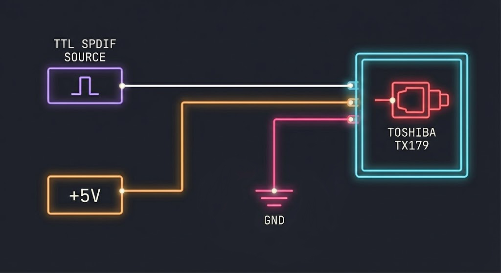
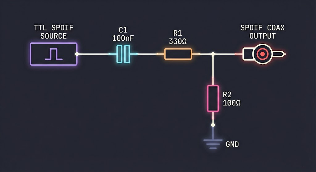
Notes: S/PDIF input requires either a Toshiba TORX141 optical receiver or a suitable receiver circuit. Possible receiver circuits are described by ST Microelectronics here. S/PDIF output requires either a Toshiba TX179 optical transmitter or a simple resistor divider. I2S output is a standard 24-bit-in-32-bit left-justified frame — wires straight into most I2S DACs. PDM output is a 1-bit logic signal that requires a resistor and capacitor to form a low-pass filter for conversion to analog audio.
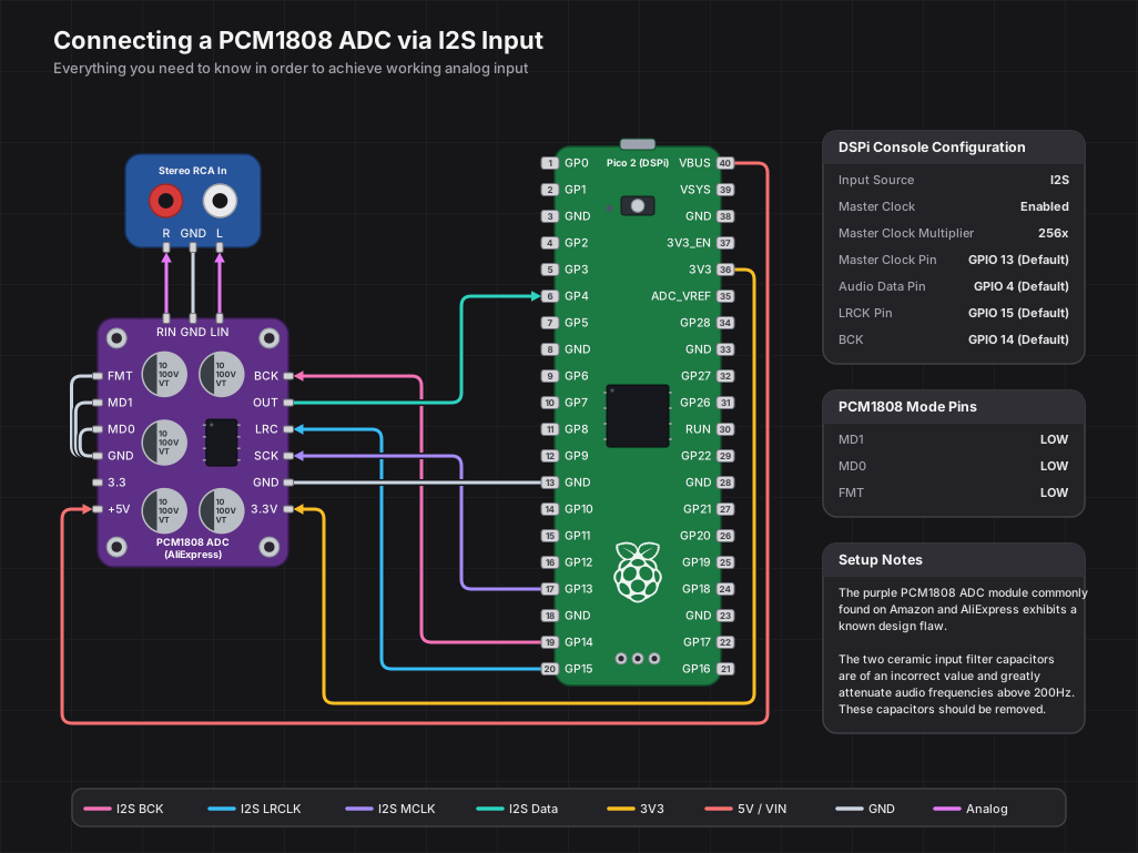
Use the PCM1808 in slave, standard-I2S mode: MD1 = LOW, MD0 = LOW, and FMT = LOW. In DSPi Console, select I2S as the input source, set RX data to GPIO 4, keep BCK on GPIO 14 (GPIO 15 is LRCLK), enable MCK on GPIO 13, and set the MCK multiplier to 256x. That gives the PCM1808 SCKI/MCLK frequencies of 11.2896 MHz at 44.1 kHz, 12.288 MHz at 48 kHz, and 24.576 MHz at 96 kHz.
PCM1808 modules vary: some expose separate VDD/3V3 and VCC/5V pins, while others have a regulator and only expose VCC. Follow the module silkscreen for power, keep all digital I/O at 3.3 V logic, and always share ground with the Pico 2.
All default pin assignments above work out of the box, but every output pin — including I2S BCK and MCK — can be reassigned at runtime through the DSPi Console application. No reflashing required. This is useful when designing custom PCBs or adapting to boards where the default GPIOs are inconvenient.
Pin assignments are saved to flash and restored automatically at boot. A few GPIOs are reserved and unavailable for output use: GPIO 12 (UART TX) and GPIOs 23-25 (power control and LED). LRCLK is always pinned to BCK + 1 due to a PIO side-set constraint.
---
The matrix mixer routes the USB stereo input to all output channels. RP2350 has a 2x9 matrix (9 outputs), RP2040 has a 2x5 matrix (5 outputs). Each crosspoint (input/output pair) has:
RP2350:
| Mode | Available Outputs | Core 1 Usage | |------|-------------------|--------------| | PDM enabled (Out 9 on) | Out 1-2 (S/PDIF 1) + Out 9 (PDM) | Delta-sigma modulator | | PDM disabled (Out 9 off) | Out 1-8 (S/PDIF 1-4) | EQ worker for Out 3-8 |
RP2040:
| Mode | Available Outputs | Core 1 Usage | |------|-------------------|--------------| | PDM enabled (Out 5 on) | Out 1-2 (S/PDIF 1) + Out 5 (PDM) | Delta-sigma modulator | | PDM disabled (Out 5 off) | Out 1-4 (S/PDIF 1-2) | EQ worker for Out 3-4 |
When the PDM subwoofer is active, Core 1 is fully dedicated to the delta-sigma modulator, so higher-numbered S/PDIF outputs are unavailable. When PDM is off, Core 1 runs as an EQ worker processing those outputs in parallel with Core 0.
Common Configurations (RP2350):
| Use Case | Routing | Mode | |----------|---------|------| | Stereo + Sub | L→Out1, R→Out2, L+R→Out9 | PDM on (3 outputs) | | 2-Way Active | L→Out1(tweeter), L→Out3(woofer), R→Out2(tweeter), R→Out4(woofer) | PDM off (4 outputs) | | 3-Way Active | As above, plus mid-range on Out5-6 | PDM off (6 outputs) | | 4-Way Active | As above, plus super-tweeter on Out7-8 | PDM off (8 outputs) |
Common Configurations (RP2040):
| Use Case | Routing | Mode | |----------|---------|------| | Stereo | L→Out1, R→Out2 | PDM off (2 outputs) | | Stereo + Sub | L→Out1, R→Out2, L+R→Out5 | PDM on (3 outputs) | | 2-Way Active | L→Out1(tweeter), L→Out3(woofer), R→Out2(tweeter), R→Out4(woofer) | PDM off (4 outputs) |
Each band can be set to any of these 14 types. Every type uses a corner/center frequency; Q and gain apply only where listed (other types ignore them).
| Type | Order | Parameters | Description | |------|-------|------------|-------------| | Flat | - | - | Bypass; the band does nothing (auto-skipped for zero CPU) | | Peaking | 2nd | freq, Q, gain | Parametric bell; boost or cut centered on freq, width set by Q | | Low Shelf | 2nd | freq, Q, gain | Boost/cut everything below freq; Q sets the transition slope | | High Shelf | 2nd | freq, Q, gain | Boost/cut everything above freq; Q sets the transition slope | | Low Pass | 2nd | freq, Q | 12 dB/oct rolloff above freq; Q sets corner resonance | | High Pass | 2nd | freq, Q | 12 dB/oct rolloff below freq; Q sets corner resonance | | Notch | 2nd | freq, Q | Deep, narrow null at freq; Q sets width | | All-Pass | 2nd | freq, Q | Flat magnitude; rotates phase 0 to -360 deg (phase / group-delay tool) | | First-Order All-Pass | 1st | freq | Flat magnitude; rotates phase 0 to -180 deg (-90 deg at freq) | | First-Order Low Shelf | 1st | freq, gain | Gentle 6 dB/oct low shelf; monotonic, no Q or overshoot | | First-Order High Shelf | 1st | freq, gain | Gentle 6 dB/oct high shelf; monotonic, no Q or overshoot | | Linkwitz Transform | 2nd | freq (f0), Q (Q0), gain (fp in Hz), target Q | Replaces a driver's measured sealed-box rolloff (f0, Q0) with a target alignment (fp, Qp) for bass extension; see PEQ filters | | First-Order Low Pass | 1st | freq | Gentle 6 dB/oct rolloff above freq; -3 dB at freq, no resonance | | First-Order High Pass | 1st | freq | Gentle 6 dB/oct rolloff below freq; -3 dB at freq, no resonance |
Frequency ranges from 10 Hz to 0.45xFs; Q from 0.1 to 20. First-order types are single-pole (6 dB/oct) and have no resonance.
On RP2040, all filters use biquad IIR (Transposed Direct Form II) with Q28 fixed-point arithmetic. On RP2350, the firmware uses a hybrid SVF/biquad architecture: filters below Fs/7.5 (~6.4 kHz at 48 kHz) use the Cytomic SVF (linear trapezoid) topology for superior numerical accuracy at low frequencies, while higher frequencies use traditional TDF2 biquad. Flat bands (and zero-gain peaking/shelf bands) are automatically bypassed for zero CPU overhead.
Channel Layout:
RP2350 (11 channels):
| Channel | Index | EQ Bands | |---------|-------|----------| | Master Left | 0 | 10 | | Master Right | 1 | 10 | | Output 1-8 (S/PDIF) | 2-9 | 10 each | | Output 9 (PDM Sub) | 10 | 10 |
RP2040 (7 channels):
| Channel | Index | EQ Bands | |---------|-------|----------| | Master Left | 0 | 10 | | Master Right | 1 | 10 | | Output 1-4 (S/PDIF) | 2-5 | 10 each | | Output 5 (PDM Sub) | 6 | 10 |
In addition to the parametric bands above, every output channel has up to 4 dedicated crossover filter bands for building active multi-way speaker and subwoofer systems. Crossover filters are low-pass or high-pass only and are tuned by corner frequency alone (Q and gain are not used). Three families are available:
| Family | Orders | Slopes | Character | |--------|--------|--------|-----------| | Linkwitz-Riley (LR) | 2, 4, 6, 8 | 12 / 24 / 36 / 48 dB/oct | -6 dB at the corner; an LP and HP pair at the same frequency sum to flat magnitude. LR4 (24 dB/oct) is the de-facto studio and hi-fi standard. | | Butterworth (BW) | 1-8 | 6 / 12 / 18 / 24 / 30 / 36 / 42 / 48 dB/oct | -3 dB at the corner; maximally flat passband. BW1 is a gentle 6 dB/oct first-order slope. | | Bessel (BES) | 2, 4, 6, 8 | 12 / 24 / 36 / 48 dB/oct | Maximally flat group delay for the best transient response and phase behavior. |
Each crossover filter is built from a cascade of up to four biquad sections. On RP2350 the same hybrid rule applies per section (sections below Fs/7.5 use the Cytomic SVF for low-frequency accuracy). Crossover bands exist on output channels only, separate from and in addition to that channel's 10 parametric bands. A typical 2-way active speaker drives one output through a high-pass crossover (tweeter/mid) and another
→ →
→ →
→ →
→ →
→ →
→ →
→ →
→